UML Diagrams
In the field of software engineering, the Unified Modeling Language (UML) is a standardized specification language for object modeling. UML is a general-purpose modeling language that includes a graphical notation used to create an abstract model of a system, referred to as a UML model.
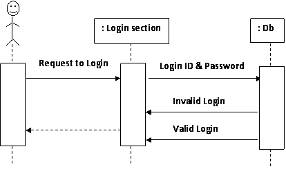
A sequence diagram will denote the sequence of steps performed by the user while using the application.
|
Fig A Sequence Diagram showing Login of user
Conceptual Diagrams of Use cases:
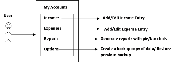
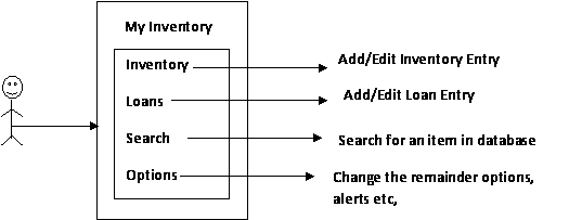
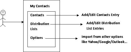
A use-case diagram denotes the possible operations a user can perform at the given context of the application.
|
||||
|
||||
Fig: Showing Conceptual Level Diagram of My Accounts Module
|
Fig: Showing Conceptual Level Diagram of My Inventory Module
|
Fig: Showing Conceptual Level Diagram of My Contacts Module
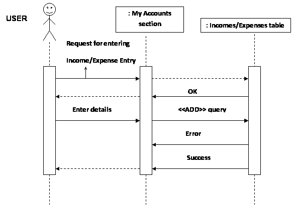
Fig: Sequence Diagram showing Add Income/Expense Entry in Accounts section
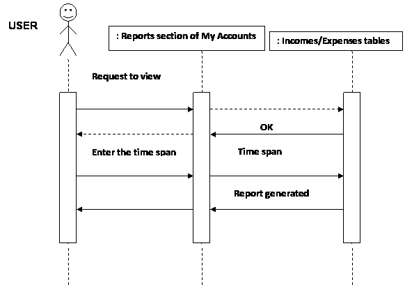
Fig : Showing Sequence diagram for generating Reports of Accounts section
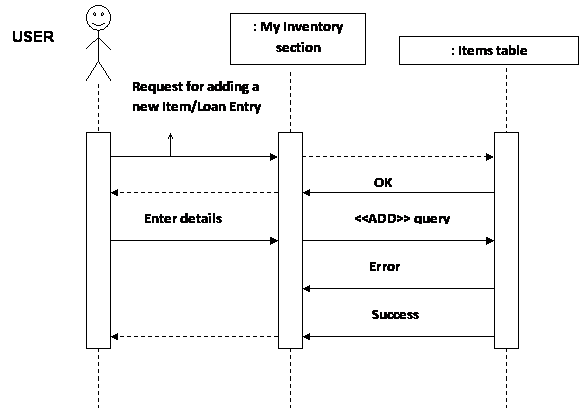
Fig: Sequence Diagram of entering Inventory/Loan Items into Inventory section
|
|
||||||
|
|||||||
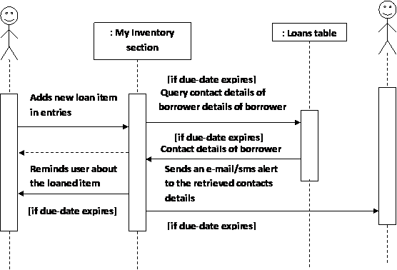
Fig: Sequence diagram of notifying user & borrower about the loan item
